
Williams Brothers 1/8 Wright J-5 "Whirlwind" Engine - Part 5
By Rogerio "Rato" Marczak
Now the wires connecting the harness loom with the distributor blocks have to be attached. This is a delicate step, as there´s the risk of scratching the paint on the wires. I used a rounded lip plier to help, but in the end I had to retouch a couple of spots. Here is the result so far:
The first wires connected.
Next I turned my attention to those wires connecting the spark plugs to the magnetos. They were made as described in part 4, except that now they are separated pieces and so more easily handled. After casting the eighteen new spark plug pipes, I painted them using the late Aeromaster tire black color. I also drilled the ends of the advance link rods and painted them gloss black with steel heads.
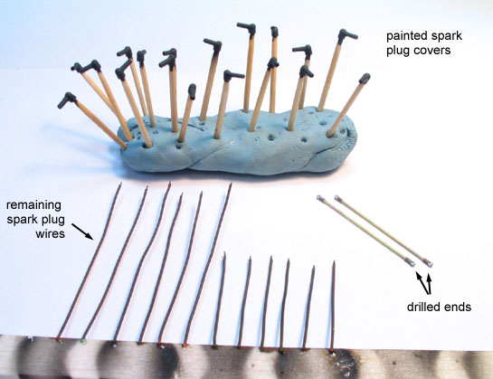
Other ignition wiring bits and the advance link rods.
The wires were then cut with the correct length and attached to the pipes. They have different lengths, so I used the orignal kit part as a template. Since the rear and front spark plug wires exit the harness loom together, they are attached with metal clips in most radial engines. I made them using thick slices of black electrical wire insulation. These tied each couple of wires - no glue needed.
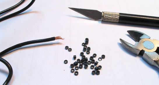
Making the spark plug wire ties.
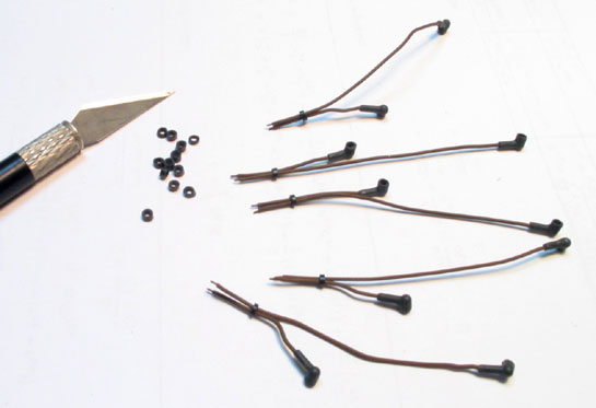
Wire assemblies ready to be installed.
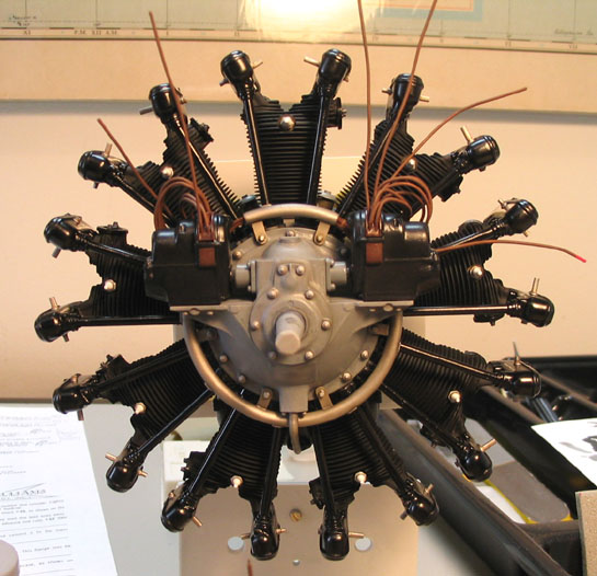
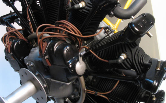
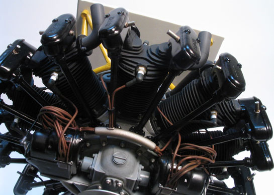
Each assembly was placed in its correct harness loom hole and spark plug (refer the last page of the instructions to avoid problems here - each cylinder is a different story). The longer wires attach the rear spark plug while the shorter attach the front of the corresponding cylinder. The natural irregular shape of the wires resulting from handling the parts gave a convincing aspect to the model. The wires were tarnished with black pastel chalk in some places, and a black wash was applied on the distributor blocks. Here it is:
Wiring finished... at last.
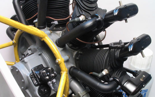
Rear spark plug wiring. I know, I know, they should be tied somewhere...
I forgot to mention that when dry fitting the magnetos to their position, I noted a large gap resulting from the reduction case assembly (I really mean large: 1+ mm). I was aware of them since the beginning of the project, but I thought they would be eventually hidden by the magnetos. A made two fake plates from thin plastic card to blank off the openings. You can´t say they are not part of the kit, but if you are going to build this model, be warned.
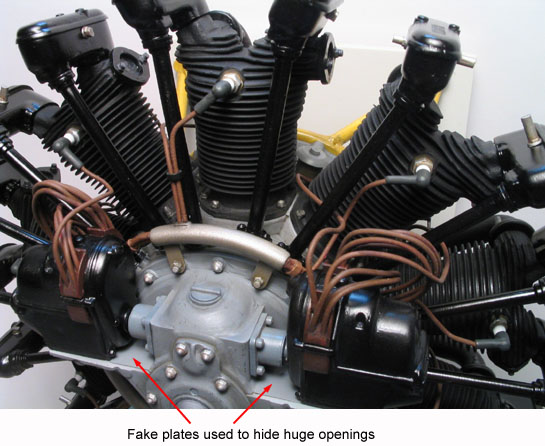
Hiding the huge gaps on the magnetos bed.
The next step was to build a new hot air intake hose for the carburetor. I made it from pieces of plastic tubing, repeatedly dry fitted against the exhaust pipes of cylinders 5 and 6.
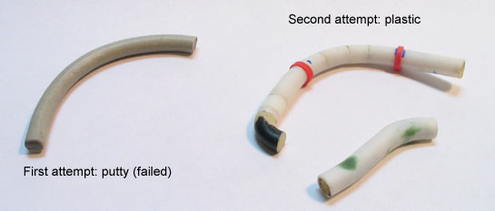
Starting a new hot air hose from scratch.
To simulate the flexible part of the hoses, I coiled plastic strips around a core tube of about the same diameter of the hose. Small drops of super glue secured the strips ends. Next, the whole thing was dip in boiling water for some minutes, and then let to cool at room temperature. The coil now can be removed from the core, resulting in a perfectly cylindrical spring.
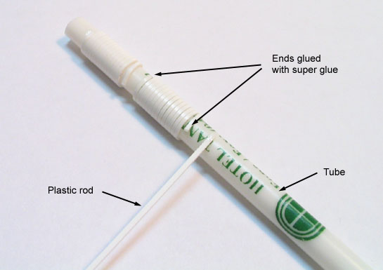
Let´s make a coil from plastic.
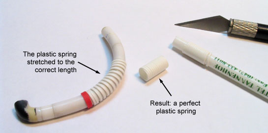
Here is the result.
The springs were cut using Eyeball Mk.1 and inserted in the corresponding hoses. The ends of them were glued to collars previously positioned along the hoses. By stretching the springs, you regulate the spacing between each coil. Once satisfied, I brushed a good coat of MEK to seal them in place. Joining both arms of the hose proved to be difficult. I first attached the longer arm to the carburetor air intake and the number 5 cylinder exhaust using tiny droplets of superglue. Once in place, I glued the short arm and adjusted its position with number 6 cylinder exhaust while the glue was still soft.
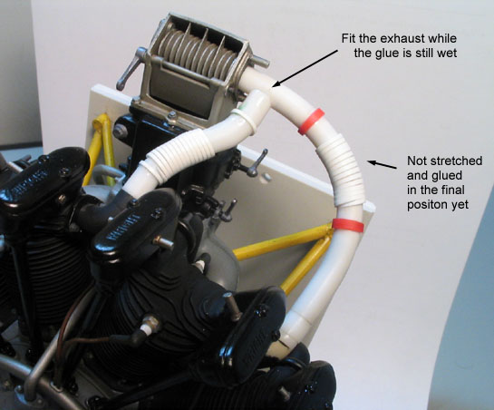
Fine tuning the hot air hoses.
Once the glue has dried, I detached the assembly from the engine and painted it with rubber black color. The raised details were highlighted with grey artist´s oil drybrushed over the coiled area. Here is how it looks:
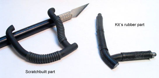
The new hot air hose (left) and the original kit rubber part (right).
I finished other smaller details, including a couple of thin aluminum strips (from soda can) to help to hide the seams of the distributor blocks. So, here are the last parts of the kit (except for the exhaust pipes):
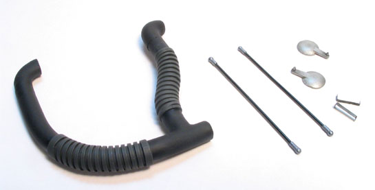
The last details to be installed.
I entered the last stage of this project cementing the scratchbuilt hot air hose in its position:
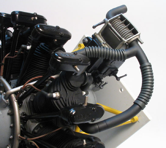
The hot air hose cemented in place.
I then proceeded to the exhaust pipes. Vintage photos of aircraft powered by the J-5 show that the exhaust pipes are generally not aligned to the thrust axis of the engine. Instead, they are angled outward. I placed them about 40 degrees with respect to the thrust axis. Once the glue has dried, they were ´dusted´ with grey and red-brown pastel chalk. The openings of the pipes were cleaned on the inside with a cotton swab lightly moistened to preserve the black color.
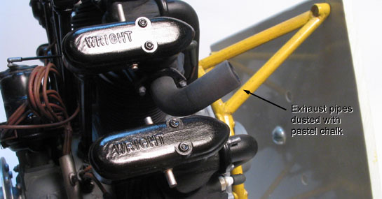
The exhaust pipes glued and weathered.
Next, the magnetos advance levers were glued in place. I had to check carefully their correct position to assure the advance rod links would reach both the lever and the pivot rod on the rear part of the engine. I used slow setting epoxy glue to allow plenty of time to work. After double checking this, the rod links were secured in place.
The right magneto advance lever and rod link in place.
The last part - so to speak - to be attached was the manufacturer plate provided with the kit>. You have to trim it to the correct size, using the plate molded on the engine crankcase drive. The plate itself is very well black printed over silver adhesive paper, and gives a formidable touch to the model.
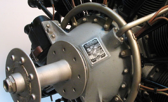
The manufacturer data plate stuck in place.
And here are some pictures of the finished model before going to its definitive base:
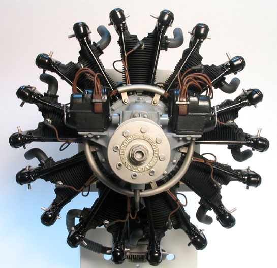
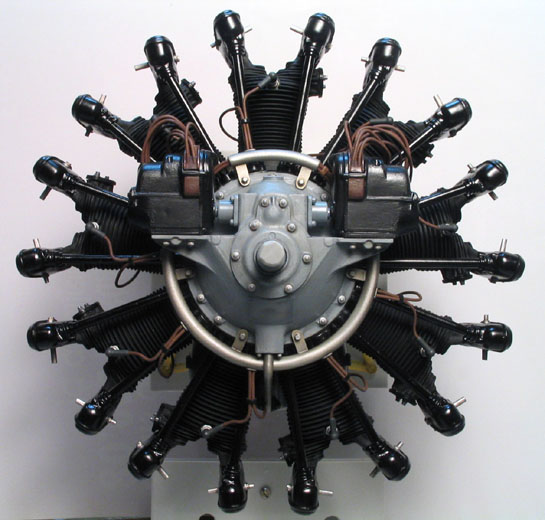
The finished model - front view.
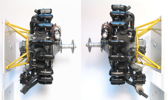
The finished model - left and right views.
The finished model - top and bottom views.
The finished model - front upper view.
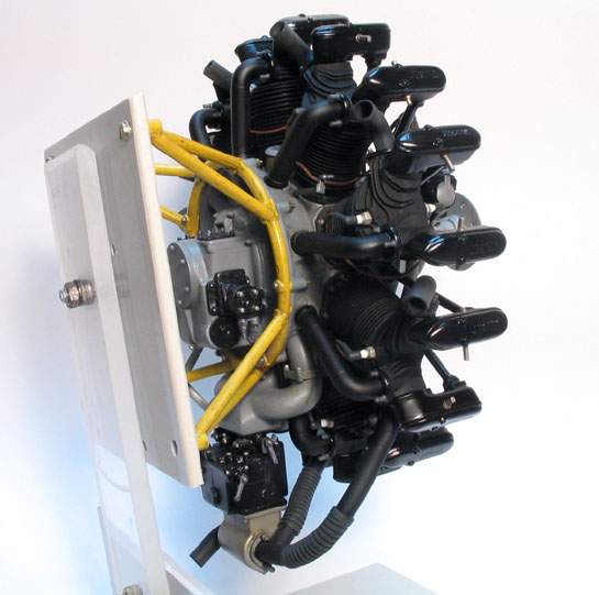
The finished model - rear quarter view.
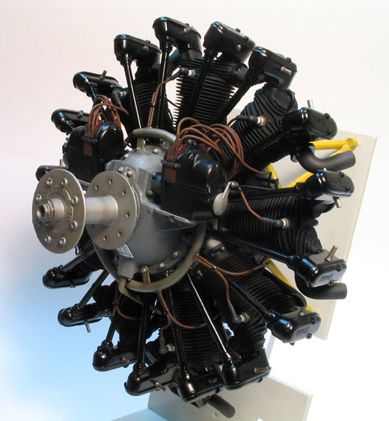
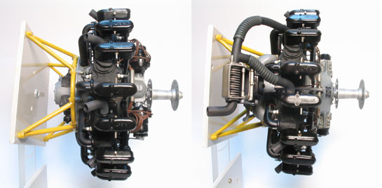
The finished model - front right quarter view.
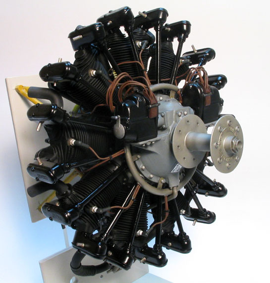
The finished model - front left quarter view.
The engine was placed on a commemorative display base along with my heavily modified Testors Ryan NYP - Spirit of St Louis in 1/72 scale.
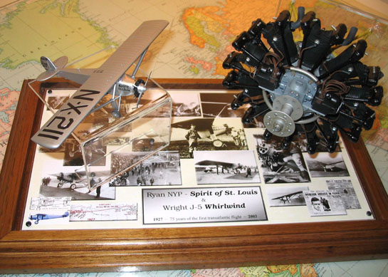
The finished project.
Well, this project was way different from everything I have ever made: no guns, no swastikas, no kill markings... But I guess the historical importance of both the J-5 Whirlwind engine and its most famous host, the Spirit of St. Louis, speaks by itself.
This was not an easy model, mostly by its lack of engineering, I´m afraid to say. However, as mentioned in the kit´s box, this is not a toy. In the present case, it provided and excellent testbed for some new techniques (for me, at least). And if something goes wrong, all you have to do is to add some grease and oil stain. I´m sure that the cheer size of the model will make anyone stop by to take a second look, regardless he/she is an aviation aficionado or not.
Recommended to anyone, specially if you are recovering from AMS, like me.
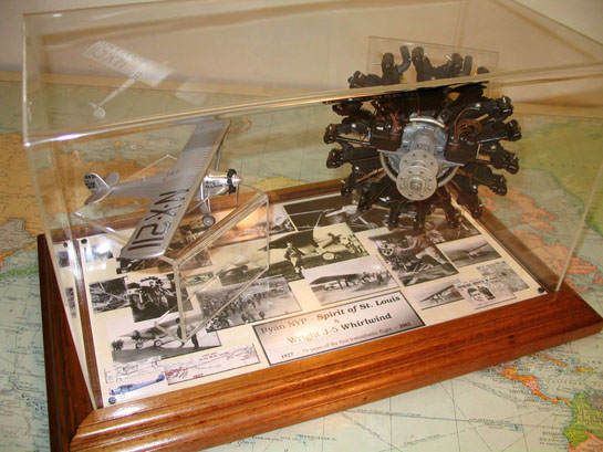
The finished project.
Part 1 | Part 2 | Part 3 | Part 4 | Part 5
© Rogério ´Rato´ Marczak
This article was published on Wednesday, July 20 2011; Last modified on Saturday, May 14 2016