
Williams Brothers 1/8 Wright J-5 "Whirlwind" Engine - Part 4
By Rogerio "Rato" Marczak
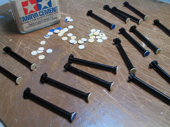
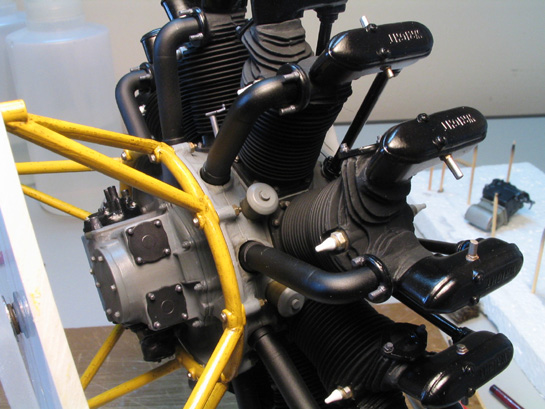
As I said in part 3, the kit has no sort of fixture to install the engine on its mount. During a CAP mission in a watch repair shop I found a good alternative: tiny metal nuts and bolts. They are chrome plated (too bright), so they will be painted over with flat clear. In addition, they are too short to pass all the way through the engine mount section and mount structure holes. My plan is to glue the engine on the mount using regular cement and place these mini-bolts capping the holes as a decorative measure.
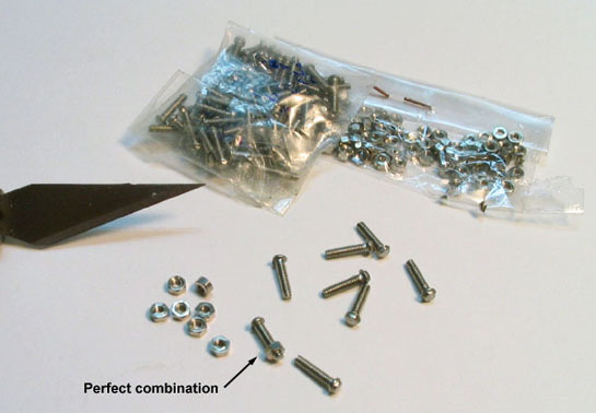
The metal nuts & bolts used.
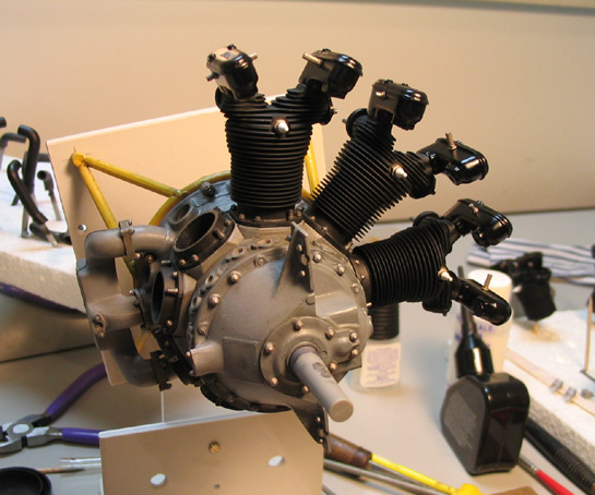
But before installing the bolts, I attached the #1 cylinder. Wow, now we´re talking about engines.
One down, eight to go...
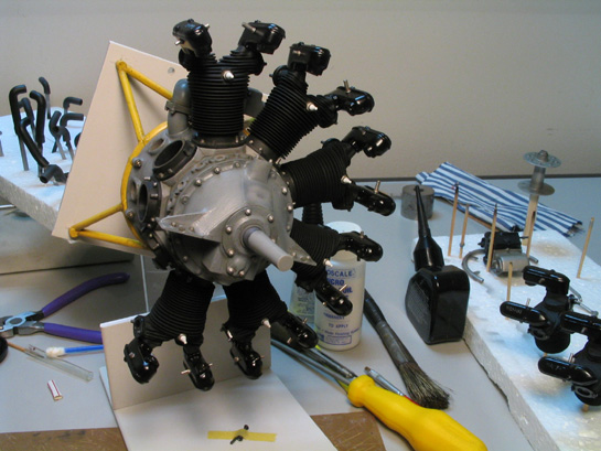
Next I installed the nuts/bolts around the engine mount arc. They were brushed with flat clear and washed afterwards. I then proceeded with the remaining cylinders, always checking the alignment. It may seem stupid to mention it here, but the cylinders have no alignment pin or slots to ensure a proper fit. To make things a bit worse here, the cylinders rest very loosely on the bases. Anticipating problems with the pushrods, I shortened the cylinder bases by sanding each one of them on a glass mounted piece of rough sandpaper.
The nuts/bolts installed.
Another view.
Three down, six to go...
Six down, three to go... aaaand...
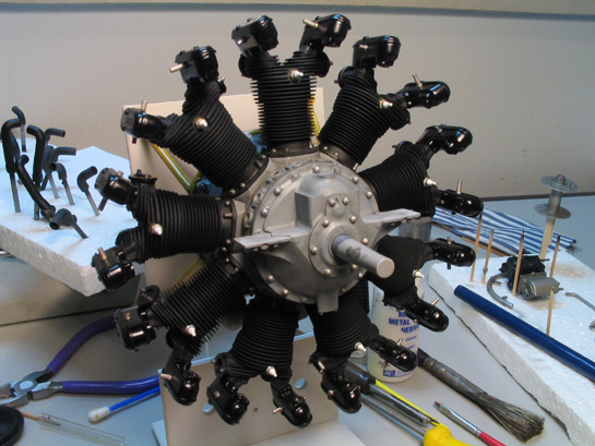
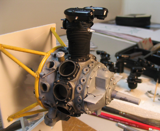
... done. Now we have an engine, eh?
Alignment is critical. Check it before the glue sets.
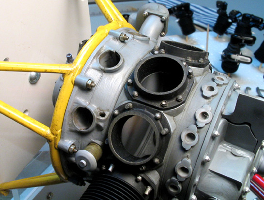
The pushrods were the next parts to be installed in place. After waiting the cylinders glue to dry, I discovered that all the pushrods were too short to fit between the pushrod pads and the bottom of the rocker boxes. Even after sanding the cylinder bases every pushrod remained about 0.5 mm too short. To solve the problem, I punched plastic discs and cemented them at the end of each pushrod. Of course I had to retouch the area with gloss black paint. The fit was much better then, and I installed the right pushrod of each cylinder first, then the left ones.
Lengthening the pushrods.
Right pushrods installed
All pushrods installed
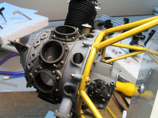
At this point I discovered that, for some reason I still don´t understand, a wedge shaped gap remained at the pushrod attachment point of each left rocker box. They were quite visible for some cylinders, but putty was out of question. I then mixed carpenters (wood) glue with gloss black Gunze acrylics (H2) and carefully filled each gap using a fine pointed brush. In some places a second application was needed. The excess was removed with a moistened cotton swab. Because carpenters glue shrink much less than regular white glues (and dries faster, too), it is virtually impossible to say where was filled.

These gaps occurred with left pushrods of each cylinder.
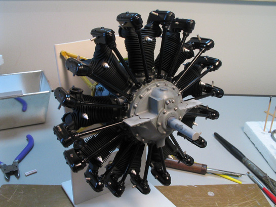
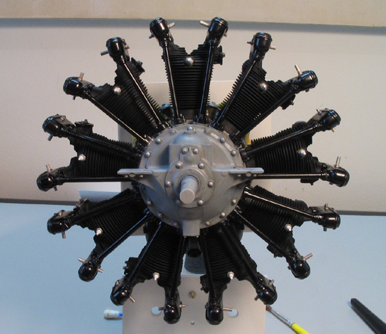
And so I finished with the pushrods. Not a smooth assembly, sure. I think the kit lacked a bit of engineering here...
After applying the white glue/gloss black mix, the gaps are nicely dissimulated.
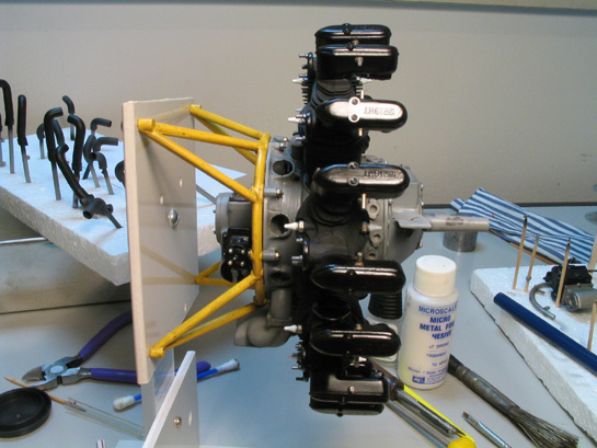
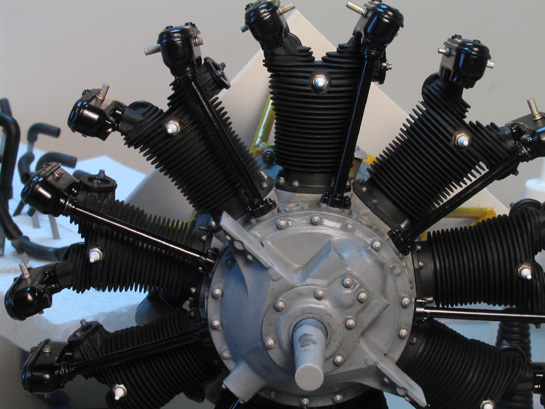
The next step was the installation of the intake pipes. They fit nicely to their flanges, so I placed a small pool of cement in each flange and installed the pipes. The other end (the one which enters the distribution housing) was simply inserted in their holes.
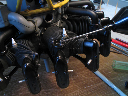
A small pool of liquid cement was applied to each intake flange.
I must confess that the idea of differential application of flat and gloss black on the intake pipes (see part 1) really gave a nice touch here. It was an enjoyable project so far... at each new part installed, it looked a bit more like an engine.
All intake pipes installed.
Before going on, I had to stop and take care of a few smaller details. Firstly, I needed eighteen new spark plug pipes. I selected three pipes cut from the kit rubber parts (the only reasonably in shape) and prepared the silicon molds. After a half dozen resin pouring sections, I got my 18 new resin pipes. They were cleaned and drilled at both ends to fit the spark plugs and the new ignition wires.
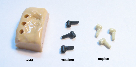
Avoiding rubber parts again: the spark plugs pipes. You need eighteen resin copies.
Another thing I had to take care of was the advance link rods. I broke one of them during their removal from the sprues. The kit parts are not bad, but I lost the broken end and decided to make a new pair of them. Using the kit part as a guide a length of brass rod was cut, and small sections of brass tubing were telescoped at the ends. The spherical hinge at the ends were made by a novel method (to me, at least): small balls of solder. Just melt solder wire on a rubber pad by holding the solder point over the melted wire for some seconds. I had to make quite a few of them only to select the four with roughly the same diameter. They were then superglued at the ends of the rods. The joints were smoothed with a coat of Mr Surfacer, and the excess wiped out with isopropyl alcohol.
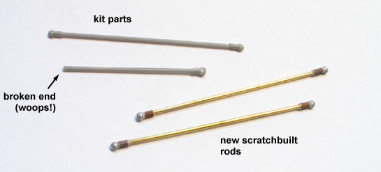
The kit´s advance link rods and the corresponding scratchbuilt items.
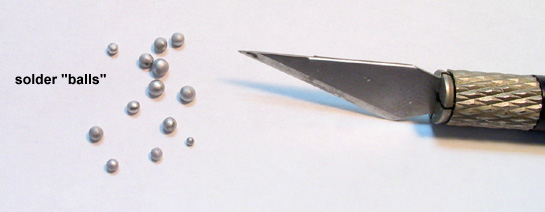
Small spheres made from solder.
Then I proceeded to the new ignition wires. I started with cooper wire. Bad idea. While a single wire is easily bendable, when you group three or four of them is another story, and I thought it would be impossible to conform a sheaf of them in the tight space behind the magnetos. Then the cooper wires were replaced by telephone wire. Much better: more easily bendable and the thickness seems to be more correct than the original rubber part. In addition, I guess it would be impossible to clean all the seam lines in the rubber item.
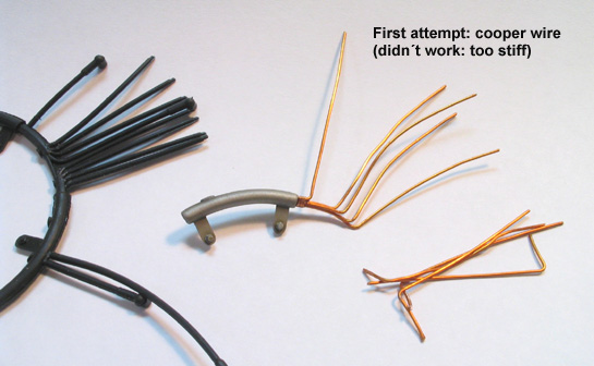
First attempt to make the ignition wires: cooper wire.
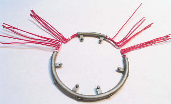
Second attempt to make the ignition wires: telephone wire.
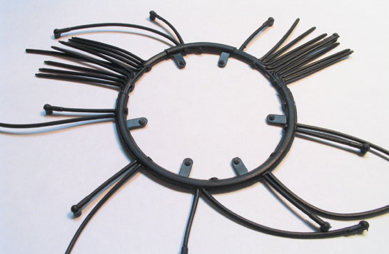
... much better than the original rubber part.
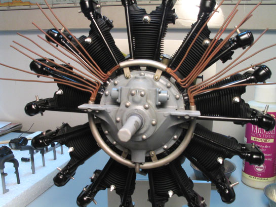
The wires you are seeing in the photos are not the only ones. They are the ones which will be inserted in the distributor blocks of the magnetos. The other wires will connect the spark plugs to the harness loom, and so they can be installed later. I used the kit part as a guide to cut the all the wires and painted them with flat brown to simulate that rusty look. Here´s another hint: these wires will be bent to their positions after painting, so enamel paint is not a good choice (you may run the risk of chipping/breaking the paint coat after all the work). I elected polycarbonate paints - very similar to the usual acrylic paints, but with a different formulation. These paints can be found in art stores, and they remain slightly flexible for many days after drying.
And then the harness loom was glued to the crankcase. I´m afraid of the next step: to bend all these wires without damaging the painted parts or breaking the fragile loom mounts.
Let´s see how it goes in the next part. Now, where the hell I placed those magnetos?
Part 1 | Part 2 | Part 3 | Part 4 | Part 5
© Rogério ´Rato´ Marczak
This article was published on Wednesday, July 20 2011; Last modified on Saturday, May 14 2016